

Published axis travel is a starting point, not a fit guarantee. On a gantry machine the usable working envelope is set by table load and clamping area, the spindle-nose-to-table distance, clearance under the cross rail, the volume guards and covers occupy, and the room your team needs to sling, clamp, datum and inspect a mould base or steel plate. Confirm each of those against dimensioned drawings and a written specification before you release an order.
What a gantry machine working envelope includes beyond axis travel
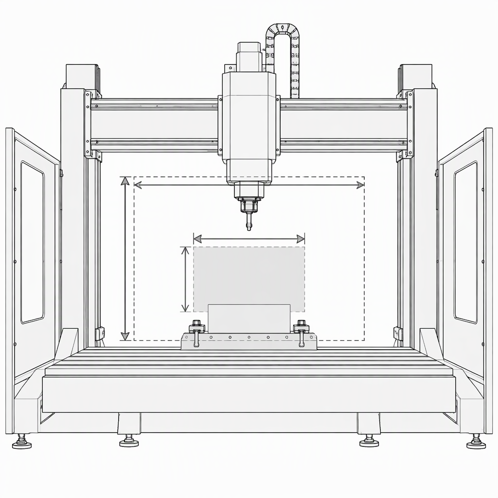
A gantry machine working envelope is the three-dimensional space a part can occupy through a complete machining cycle, together with its fixture, clamps and tooling, while the machine is guarded and ready to run. X, Y and Z travel figures only say how far the axes can move; they say nothing about the throat under the cross rail, the height a tall fixture consumes, or the access a mould base needs while it is loaded.
| Envelope dimension | What a datasheet usually gives | What you must confirm for your part |
|---|---|---|
| Table working surface | Table length and width | Whether the part plus clamping kit still leaves machinable area on every side that needs work |
| Vertical distance | Spindle nose to table, minimum and maximum | Workpiece height plus fixture, clamps and the longest tool projection, with margin left for tool changes |
| Cross-rail and portal clearance | Height under the rail or gantry bridge, often not quoted | Height of the loaded part and fixture, including anything standing proud of the plate |
| Throat and reach | Distance between columns or to the column face | Whether the head reaches far-edge features without running out of travel in Y |
| Guarding and covers | Rarely quoted as a dimension | The volume taken by guards, doors and way covers during the cycle |
| Load | Table load limit, where safe use depends on it, with a safe working load marking | Part plus fixture weight against that limit, measured rather than estimated |
| Access | Not usually quoted | Room to sling, land, clamp, datum and measure at the far edges |
How to add up workpiece, fixture and tooling inside the envelope
Build the vertical stack from the table surface upward: fixture base, clamping hardware, workpiece height and tool projection below the spindle nose. Compare that total with the spindle-nose-to-table distance at the position where the head will actually work. Whatever remains is your working clearance, and the head must still have room to retract for a tool change.
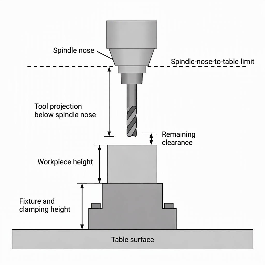
- Fix the reference point. Work from the table surface, and check whether the published vertical figure is measured at mid-travel, at the top of travel or across the whole range.
- Add the fixture. Measure the tallest combination of base plate, risers and clamps you will actually use, not the shortest.
- Add the workpiece at its tallest point, including the stock allowance on a mould base that has not yet been face-milled.
- Add the tool. Measure the projection below the spindle nose for the longest tool you intend to run.
- Compare at the working position. The vertical limit at the far side of the table may differ from the limit in the middle.
- Repeat at the extremes: tallest fixture plus longest tool, at the highest table position the work will use.
A fixture or a long tool reduces usable travel even when the part is smaller than the table. A tall fixture pushes the work towards the spindle nose, a long tool eats the distance below it, and together they can leave too little room to retract before a rapid move or a tool change. Check the stack with the worst combination you expect to run, and ask the supplier to confirm the vertical figure across the whole working area rather than at a single point.
Loading, clamping and inspection access around large plates
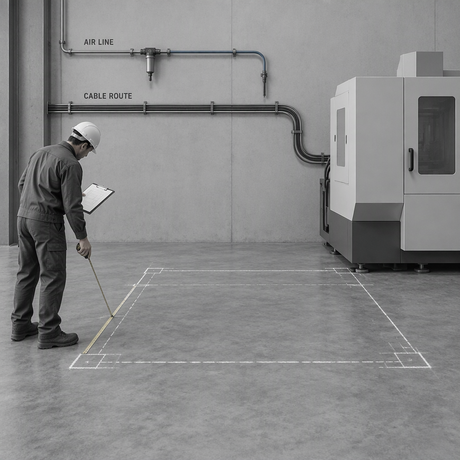
Around a large plate or mould base, the envelope must also hold the room people and lifting gear need: pick points clear of guards, enough table at both ends to land the part without overhang, clamp positions you can reach and torque, and enough travel to bring a probe or indicator to every feature you must datum.
- Confirmed part and fixture weight, checked against the table's stated limit rather than an estimate.
- Landing space at both ends of the part so slings and packing can be removed after setting.
- Clamp positions inside the table edges and clear of the guard or door line.
- Enough vertical travel to reach the deepest pocket and to retract fully for a tool change.
- A datuming and inspection route that does not require releasing the clamps you have just set.
- A door or guard opening that lets an operator reach the far side without leaning past the spindle.
If loading a heavy plate means opening a guard or releasing an interlock, that is a residual risk the supplier has to declare and you have to control. Check that the machine arrives complete with every safeguard fitted, that it is stable and fixed down as specified, and that the permitted loading procedure is set out in the manufacturer's instructions rather than improvised on the shop floor.
Installation, guarding and maintenance conditions that shrink usable space
Usable space is reduced by everything the machine has to accommodate in service: a foundation and levelling arrangement that keeps the frame stable, guards, interlocks and way covers that travel with the axes, chip and coolant management, and clear standing space at the service points the manufacturer identifies. A machine installed out of level or left unfixed is not a safe basis for a fit calculation.
In Great Britain, the duties sit with the machine user as well as the supplier. Employers there are expected to select equipment suitable for the job, confirm it is complete with all safeguards and free from defects, have static machines installed properly and made stable, and then use it as the manufacturer instructs while managing the residual risks the supplier must declare. If your site is outside Great Britain, confirm the equivalent equipment-safety requirements that apply where you operate, because the duties described here are the Great Britain position. HSE's introduction to machinery safety sets out those employer duties.
For machines placed on the EU market the applicable legislation is changing: the Machinery Directive 2006/42/EC governs machines placed on the market before 20 January 2027, and the Machinery Regulation (EU) 2023/1230, adopted on 14 June 2023, applies on a mandatory basis from that date. Check the current position on the European Commission's machinery legislation page before you fix a delivery date, because the requirements your supplier must meet depend on when the machine is placed on the market. New machinery placed on the GB market must carry UKCA or CE marking, be supplied with a declaration of conformity and have instructions in English. If you are sourcing used or second-hand machines, or importing a machine yourself, confirm the supply requirements that apply to your own transaction separately, because that marking and documentation duty attaches to new machinery being placed on the GB market.
Maintenance changes the space you need as well. Planned maintenance should follow the manufacturer's maintenance instructions, and equipment should be designed so adjustment points are reachable and access is safe. Before anyone reaches behind a guard, past a way cover or into the working area, switch the machine off and disconnect it from its power supply, and isolate stored energy such as hydraulic or pneumatic pressure; then follow only the access procedure the machine manual permits.
Documents and questions that verify the envelope before ordering
Ask for specification documents rather than a brochure: a general-arrangement drawing with dimensions, the axis travel and limits, the spindle-nose-to-table range, clearance under the cross rail, the table load limit and clamping layout, the guarding envelope, and the loading and maintenance access the machine needs. Then compare your part-plus-fixture drawing against each figure, one line at a time.
| Check | Document to request | Passes when | If it is not available |
|---|---|---|---|
| Vertical stack | Dimensioned drawing showing the spindle-nose-to-table range across the working area | Your measured stack fits with margin for a tool change at every position you use | Do not accept a single travel number; ask for a dimensioned drawing before the order |
| Cross-rail clearance | Section view showing the height under the rail or gantry bridge | The loaded part and fixture clear with the head passing over | Request a section drawing, or reduce the fixture height in your process plan |
| Load | Specification stating the table load limit and the safe working load marking | Measured part-plus-fixture weight sits below the limit | Ask for the marking value in writing before the machine is built |
| Access | Drawing of guard and door openings, plus the service and adjustment points | Slinging, clamping, datuming and maintenance are reachable in the space you have | Ask for the loading and maintenance procedure in writing |
| Documentation | Declaration of conformity and instructions in the language your market requires | They cover the exact model and match the drawing revision | Do not accept delivery until the documents are supplied |
What belongs in a gantry machine RFQ for envelope verification
Put the envelope check inside the enquiry and inside the order. Send your part drawing with the fixture and clamping plan, state the vertical stack and the load you need, describe how the part will be lifted and inspected, and ask the supplier to confirm fit in writing against a dimensioned drawing that forms part of the contract.
- Part drawing with finished sizes and stock allowance, plus the fixture and clamping arrangement.
- Maximum part-plus-fixture weight and the lifting method you will use.
- Required spindle-nose-to-table clearance with the longest tool assembled.
- Required clearance under the cross rail or gantry bridge.
- Table clamping positions you must be able to use, and any features you cannot reposition.
- Access and handling needs: door opening, crane or hoist route, datuming and inspection.
- Documents: dimensioned general-arrangement drawing, load markings, declaration of conformity and instructions for your market.
- Acceptance wording: the drawing revision is part of the order and a deviation from it is a non-conformity.
Conclusion: treat the envelope as a checked claim, not a headline number
Treat every envelope figure as a claim to be checked against your part, your fixture and the way you will load, clamp and maintain the machine. A machine that fits on paper but cannot be loaded, datumed or serviced inside its own guarding is the wrong machine, whatever travel its datasheet headlines.
- Axis travel is potential motion; the working envelope is what is left after fixture, tooling, guarding and access.
- Build the vertical stack and compare it with the spindle-nose-to-table distance at the position you will actually work.
- Check clearance under the cross rail with the tallest fixture and the longest tool assembled.
- Plan slinging, clamping, datuming, inspection and maintenance access before you compare models.
- Make a dimensioned drawing, the load markings and the instructions part of the order.
Frequently asked questions
These are the points that most often decide whether a gantry machine's envelope suits a mould base or a steel plate, and each one is settled by drawings and measurements rather than by a travel figure.
Is axis travel the same thing as the working envelope?
No. Axis travel describes how far each axis can move; the working envelope is the space left for the part once fixture, clamping, tooling, guarding and operator access are allowed for. The usable volume is always smaller than the travel figures suggest, and that difference is where selection mistakes happen.
Does CE or UKCA marking prove that a machine's working envelope suits my part?
No. Marking and a declaration of conformity show that the machine meets the market's legal requirements for being placed on the market, not that a particular mould base fits inside it. Fit is a specification question, settled with a dimensioned drawing and your own stack calculation.
Can a fixture or long tool reduce usable travel even when the part is smaller than the table?
Yes. A tall fixture raises the top of the work towards the spindle nose and a long tool takes up the distance below it, so both consume vertical margin. Long tools also leave less room at the retract position, which is where a tool change or a rapid move exposes the shortage.
Which single number should I compare between two candidate machines?
None on its own. Compare the spindle-nose-to-table range with your measured stack first, then the clearance under the cross rail, then the table load and clamping layout. A machine with more travel in one direction can still offer less usable height under its rail.
Does a larger table always mean more usable envelope?
No. A larger table adds area, but not necessarily height, throat clearance or load capacity, and a longer table can push clamp positions further from the operator. Match each dimension to the parts and fixtures you actually run.
What if the supplier will not provide dimensioned drawings?
Ask for the general-arrangement drawing, the load markings and the instructions before you commit. Without written dimensions you cannot verify fit, and an unconfirmed envelope is a commercial risk rather than a selection decision, so consider another supplier or make the drawing a condition of the order.