


If you want to get better results from your CAD designs, you need to focus on both the design and the machining process. Optimizing your CAD work helps you save time and money. Shorter machining times lead to lower costs, especially when you produce many parts. Choosing the right materials and making smart design choices, like increasing wall thickness or limiting cavity depth, also reduces expenses. Leading CNC manufacturers such as GooDa Machinery use these strategies to deliver high-quality results. Get ready to discover Tips to Improve Your CAD Designs for CNC Machining.
Simplify your CAD designs to reduce machining costs and time. Simple shapes are easier to produce and require less specialized tooling.
Avoid thin walls in your designs. Follow recommended wall thickness guidelines to ensure structural integrity and reduce scrap rates.
Limit unnecessary features in your CAD models. Focus on functionality to improve efficiency and lower production costs.
Ensure tool access in your designs. Check that all features are reachable by cutting tools to avoid errors and improve part quality.
Collaborate with CNC experts early in the design process. Sharing your design intent can lead to better manufacturability and higher quality results.
You can achieve better results by simplifying the geometry in your CAD models. Simple shapes are easier to machine and cost less. Tall features often vibrate during machining, which makes them hard to produce accurately. Rotating parts can change the aspect ratio and affect the final geometry. Complex shapes require more steps and special tools, which increases production time and cost. You should avoid deep pockets and undercuts unless they are necessary. Symmetrical designs help with fixturing and machining. GooDa Machinery uses advanced CNC solutions to handle complex geometries, but you will save time and money by keeping your designs straightforward.
Simple, well-defined geometries are easier and less expensive to machine.
Minimize undercuts and deep pockets to avoid special tooling.
Avoid intricate features unless necessary to reduce costs.
Leverage symmetry for easier fixturing and machining.
Complex geometries can lead to increased manufacturing timelines and costs.
Streamlining your CAD models is one of the best tips to improve your cad designs for cnc machining. Each line in your CAD model translates to machine movements or setup changes. Unnecessary features add time and escalate costs. When you remove these features, you reduce the need for specialized tooling and operator attention. GooDa Machinery’s expertise shows that simple designs lead to faster production and fewer errors.
Thin walls can cause problems during CNC machining. They often bend or warp under load, which affects structural integrity. Achieving tight tolerances becomes harder, and you may need extra finishing steps. Thin walls are prone to deformation, which increases scrap rates. Specialized tooling is sometimes required to prevent deflection, raising costs. Machining speeds must slow down to protect fragile features, leading to longer cycle times.
You should follow recommended wall thickness guidelines based on material type. The table below shows minimum and maximum wall thicknesses for common materials:
Material Type | Minimum Wall Thickness (mm) | Maximum Wall Thickness (mm) |
|---|---|---|
Aluminum and Plastics | 1 | 6 |
Steel and Stainless Steel | 3 | 10 or more |
Titanium | 2 | 6 |
Thin-Walled Parts | 0.5 | N/A |
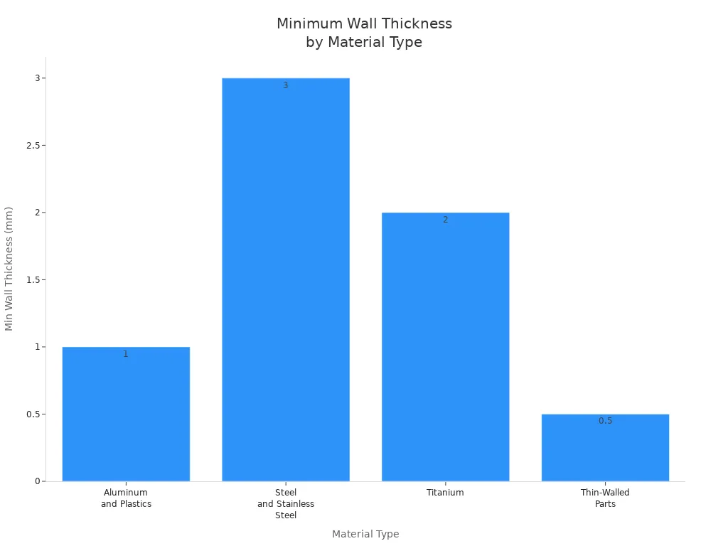
You can improve manufacturability by keeping wall thickness above 2 mm for most metals. GooDa Machinery recommends following these guidelines to ensure your parts remain strong and easy to machine. This is one of the most important tips to improve your cad designs for cnc machining.
You should always evaluate the functional requirements of your part. Remove any features that do not enhance functionality. Small features can cause tool breakage and increase machining time. Decorative elements that serve no purpose add extra steps and effort. Features like square internal corners and excessively thin walls are difficult to machine.
Minimize unnecessary features to improve efficiency.
Avoid too small features unless essential.
Minimize aesthetic features that do not serve a functional purpose.
Avoid features that are difficult to machine.
Removing features and consolidating operations leads to faster machining and lower costs. Fewer features mean reduced setups and cycle time. Many parts incur high costs because they require multiple operations. You can use these design tips to improve your cad designs for cnc machining and reduce errors. GooDa Machinery’s experience shows that streamlined designs help you achieve better results and higher productivity.
Tip: Always review your CAD model before sending it for machining. Ask yourself if every feature is necessary. This simple step can save you time and money.
You can use these tips to improve your cad designs for cnc machining and make your workflow more efficient. GooDa Machinery’s industry expertise proves that following these tips leads to high-quality parts and lower production costs.

Tool access plays a major role in CNC machining. If you design your cad model without considering tool clearance, you may face problems during production. You want every feature in your part to be reachable by the cutting tool. Sometimes, what you see in your cad software does not match what the machine can reach. This can lead to extra setups, errors, or even damaged parts. GooDa Machinery uses advanced CNC solutions to handle complex geometries, but you can make machining easier by following these guidelines.
You should always check that the spindle and cutting tool can reach all areas of your part. Here are some best practices:
Make sure the tool can access every feature without obstruction. The collet must not hit the part before the cutter reaches the area.
Use tools with the largest diameter and shortest length possible. This reduces machine chatter and improves accuracy.
Avoid deep, narrow pockets and features next to tall walls. These can cause cutter deflection and make chip removal difficult.
Remember that each rotation of the workpiece requires recalibration. This can introduce small errors and affect precision.
For deep cavities, you may need tools with extended reach. This can increase vibration and reduce accuracy.
If you design your cad model with tool access in mind, you will reduce errors and improve part quality.
Sharp internal corners are hard to machine. You should add internal radii to your cad designs. This helps the tool move smoothly and reduces wear. Here are some recommendations:
Set the internal corner radius to at least one-third of the cavity depth.
Choose a radius that matches the cutter size, ideally 130% of the tool radius or add 0.02"–0.05" for smoother results.
Start with an internal radius between 3–6 mm, then adjust based on pocket depth.
The table below shows how different features benefit from proper internal radii:
Feature Type | Minimum Radius | Recommended Radius | Manufacturing Benefit |
|---|---|---|---|
Internal corners | 0.005" (0.13mm) | 0.030" (0.76mm) | Standard tooling compatibility |
Deep pockets | 0.010" (0.25mm) | 0.060" (1.52mm) | Reduced tool deflection |
Thin wall features | 0.020" (0.51mm) | 0.080" (2.03mm) | Improved rigidity during cutting |
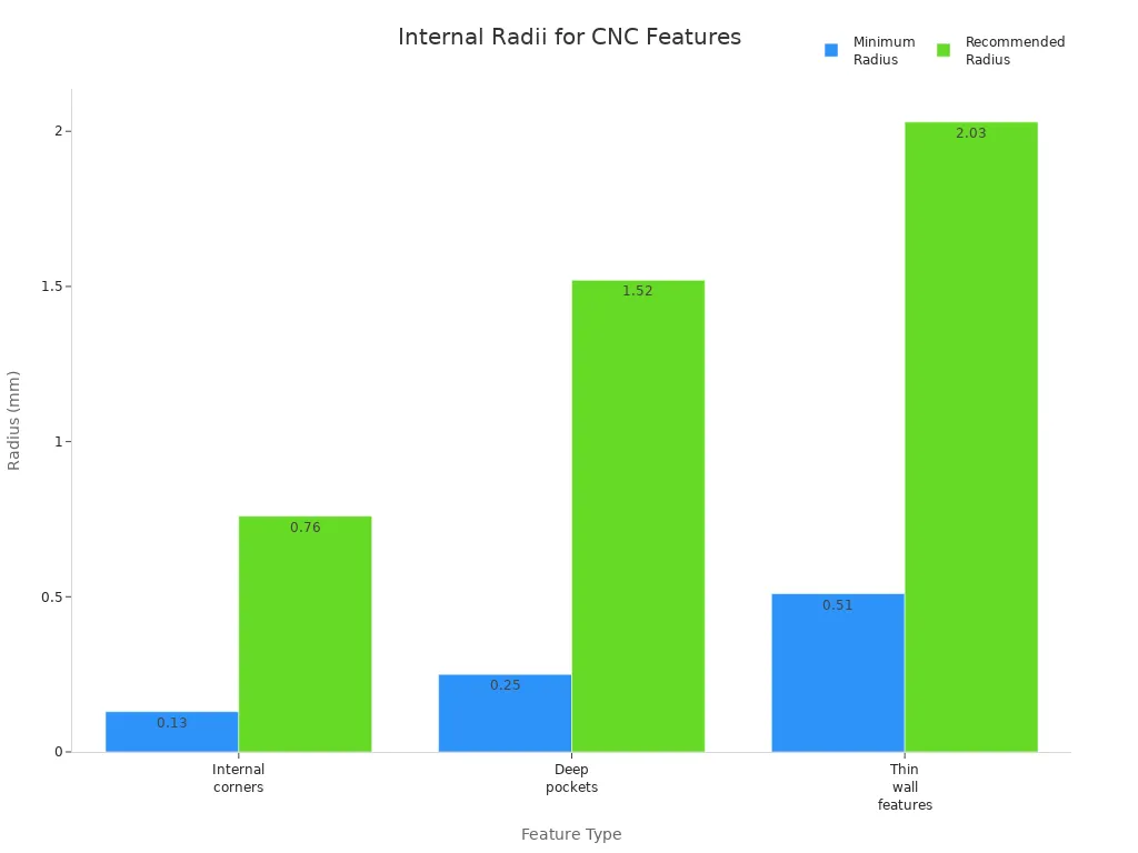
Adding proper radii in your cad model lowers the risk of tool breakage and improves surface finish.
Cavity design affects both tool access and part quality. You should keep the depth-to-width ratio of cavities within recommended limits. The best practice is to keep the maximum ratio at 1:4. If you make cavities too deep and narrow, you may face these issues:
Tool deflection and vibration, which can harm surface finish and accuracy.
Dimensional errors, such as tapered walls, even if your cad design specifies vertical walls.
Problems with chip evacuation, leading to heat build-up and tool damage.
Difficulty in delivering coolant to the cutting edge, which can worsen machining conditions.
By following these tips, you help GooDa Machinery’s CNC machines deliver precise and high-quality results. Always design with tool access and machinability in mind for the best outcome.
You need to choose materials that match your project’s requirements and machining capabilities. Aluminum 6061 stands out as a popular choice because it offers a strong balance between weight and durability. Stainless steel alloys provide excellent strength and resist wear, making them ideal for heavy-duty applications. Plastics are lightweight and work well for prototypes or parts needing chemical resistance. Material selection affects both cost and lead time. Expensive materials like titanium increase costs and slow down production. Harder materials wear out tools faster, which means you spend more on replacements. GooDa Machinery’s advanced CNC machines handle a wide range of materials, so you can select the best option for your cad project.
Aluminum 6061: Great for automotive and aerospace parts.
Stainless steel: Best for strength and corrosion resistance.
Plastics: Useful for lightweight and insulated components.

Designing your cad models with standard tooling sizes improves efficiency and lowers costs. Standard hole diameters, such as 3, 6, and 10 mm, eliminate the need for custom tools. You should keep minimum hole and tool diameters at 2.5 mm for accurate machining. Threads longer than three times their diameter are rarely needed. For blind holes under M6, leave an unthreaded section at the base. Standardizing radii and wall thickness helps you avoid thin walls, which can cause vibration and errors. GooDa Machinery’s CNC solutions work best when you use standard sizes, speeding up production and reducing waste.
Standard hole sizes and radii reduce machining time.
Larger cutting tools remove material faster and last longer.
Standardized components simplify production and shorten lead times.
Aligning features in your cad designs boosts accuracy and saves time. When you place critical features along standard coordinate planes, you make setups easier and reduce complexity. Automated part alignment cuts down manual positioning, leading to faster setups. Proper feature placement lets you use three-axis equipment throughout machining. Simulation tools help you test designs and spot problems early. Optimized tool paths minimize material waste and errors.
Benefit | Description |
|---|---|
Improved Accuracy | Automated steps enhance precision. |
Early Problem Detection | Simulations identify issues before machining. |
Increased Efficiency | Automation speeds up the process. |
Minimized Material Waste | Optimized tool paths reduce waste. |
Reduced Errors | CNC technology lowers mistakes. |
Shorter Production Time | Efficient setups cut down production time and costs. |
GooDa Machinery’s expertise ensures your cad designs align with best practices, leading to reliable and cost-effective results.
You should always set tolerances that match your design requirements and the manufacturing process. If you ask for very tight tolerances on every feature, you increase machining complexity and cost. You also make the manufacturing process longer and risk more scrapped parts. Instead, define tolerances only on critical features. This approach helps you balance precision with manufacturability and reduce production time.
Here is a table showing recommended tolerance ranges for different applications:
Application Type | Recommended Tolerance Range |
|---|---|
Press-fit hardware | ±0.0005 inches |
Complex requirements | ±0.002 inches |
General applications | ±0.05 mm to ±0.127 mm |
High accuracy parts | ±0.01 mm to ±0.025 mm |
For most general applications, a tolerance of ±0.05 mm to ±0.127 mm works well. You should avoid over-tolerancing, as it can lead to impractical production scenarios. Collaborate with your machining partner to review tolerances and ensure you meet your design requirements without adding unnecessary steps.
Tip: Optimizing product design by setting realistic tolerances helps you improve quality and keep costs under control.
A successful cad model starts with a clean and accurate file. You need to check all measurements and make sure they match your design requirements. Avoid thin walls that can cause problems during the manufacturing process. Align your sketches properly to reduce errors. Add clear annotations and specifications so machinists understand your intent. Always perform a quality check by having another person review your cad drawing before sending it to production.
A clean file environment also prevents dust and impurities from affecting your parts. This step keeps your manufacturing process smooth and helps you achieve better results.
Steps for preparing clean cad files:
Check all dimensions for accuracy.
Follow minimum wall thickness guidelines.
Align sketches and features correctly.
Add detailed notes and specifications.
Ask someone else to review your file for a quality check.
Optimizing product design at this stage ensures a smooth transition from design to manufacturing.
You must export your cad files in formats that work well with CNC machines. Common formats include DXF, DWG, and STL. Each format has its strengths and limitations:
File Format | Advantages | Limitations |
|---|---|---|
DXF | Widely supported, flexible for editing | Limited to 2D geometry |
DWG | Supports 2D and 3D, industry standard | Proprietary, can be complex |
STL | Good for complex shapes, universal compatibility | Mesh-based, less precise, hard to edit |
Choosing the right format helps you optimize product design and reduce errors during the manufacturing process. Compatible formats ensure your files integrate smoothly with CNC software, preserve accuracy, and support efficient workflows. GooDa Machinery supports a wide range of cad file formats and offers advanced solutions for precision machining. This support helps you achieve a seamless transition from design to manufacturing.
Note: Always confirm the preferred file format with your CNC partner before exporting your cad files.
You can boost productivity by designing your parts for minimal setups. Each time you reposition a part, you add time and increase the chance for mistakes. Fewer setups mean you spend less time on alignment and more time making quality parts. When you design for single clamping operations, you improve accuracy and reduce errors.
Here are some advantages of designing for minimal setups:
You reduce complexity in machining processes.
You lower costs because you need fewer setups.
You improve efficiency with single clamping, which enhances accuracy and minimizes error risks.
You should always look for ways to combine features on the same side of a part. This approach lets you complete more machining steps in one setup. GooDa Machinery’s advanced CNC solutions help you achieve this goal. Their machines support multi-face machining, which means you can finish more work without moving the part. This saves time and ensures consistent quality.
You need to think about how your part will be held during machining. Workholding is just as important as tooling or programming. If your part bends under clamping pressure, you cannot achieve high precision, even with the best tools.
Designing parts with clamping in mind is essential. Flat and accessible surfaces make the clamping process simple. Consistent datum surfaces are crucial for alignment, especially in multi-setup operations.
Flat surfaces allow for secure clamping.
Accessible areas make it easy to position the part.
Consistent datum points help with accurate alignment.
GooDa Machinery offers workholding solutions that support efficient setups. Their machines use advanced fixtures and clamps to keep your parts stable. You get better results when you include clamping surfaces in your CAD designs. This step helps you achieve high precision and repeatability in every project.
Tip: Always review your CAD model to check for flat, accessible clamping surfaces before sending it to production.
You should always share your design intent with CNC machinists early in the process. This step helps you get the best results from your CAD designs. When you explain the purpose of your part, machinists can suggest ways to improve manufacturability. You do not need to wait until your design is finished. Early conversations save time and prevent costly mistakes.
Engage machinists at the start of your project. Their experience can help you avoid common design issues.
Share your goals and not just the technical drawings. Machinists can offer ideas to make your part easier to produce.
Discuss how you will measure and inspect your part. This ensures the shop can meet your tolerance needs.
Review material choices together. Machinists know how different materials behave during machining.
Set tolerance requirements that match the shop’s capabilities. This step helps you avoid delays and extra costs.
GooDa Machinery’s technical support team works closely with customers to understand their design intent. You can use their expertise to make sure your CAD models are ready for efficient CNC machining.
You should always ask for feedback on manufacturability before finalizing your CAD design. CNC experts can spot problems that you might miss. Their advice can help you improve your design and reduce production time.
Use advanced 3D modeling software like SolidWorks® or Inventor®. These tools have features that make the transition from CAD to CNC smooth.
Work with engineers who combine CAD skills with hands-on machining experience. This teamwork leads to better solutions.
Collaborate with product designers and machinists. Joint reviews often result in designs that are easier and less expensive to manufacture.
Choose CAD software that supports precision and follows industry standards. This ensures your drawings are clear and consistent.
GooDa Machinery encourages you to share your CAD files and ask for feedback. Their team can help you optimize your design for their advanced CNC machines. Early and open communication leads to higher quality parts and a more efficient workflow.
You now have indispensable tips for designing for manufacturing with CNC machining. Apply these strategies to your CAD designs to boost efficiency and reduce costs.
Review your models for simplicity and machinability.
Choose materials and features that support easy production.
Collaborate with CNC experts like GooDa Machinery for the best results.
Continuous improvement in your CAD process leads to higher quality and greater productivity.
You should focus on how your design will affect manufacturing. Simple cad models help you avoid errors and reduce costs. Always check tool access and make sure your features match standard machining practices. This approach improves cnc machining results and speeds up manufacturing.
Material selection affects every step of manufacturing. Softer materials like aluminum make machining faster and easier. Harder materials increase tool wear and slow down production. You should always match your design to the right material for efficient manufacturing and high-quality cnc machining.
Over-tolerancing makes manufacturing more complex and expensive. You should only set tight tolerances for critical features. This practice helps you balance quality and cost. It also allows for smoother machining and reduces the risk of errors during manufacturing.
You can group features on the same side of your part. This reduces setups and saves time in machining. Always include flat surfaces for clamping. Efficient design choices lead to faster manufacturing and better cnc machining results.
You should ask for feedback early in your design process. CNC experts can spot manufacturing challenges before you finish your cad models. Their advice helps you avoid costly mistakes and ensures your design is ready for efficient machining and manufacturing.


